FIRE HYDRANT, DRY BARREL, 250 PSI / PN17,2, ALL AISI316
UL/ULC listed, FM approved, modern type, lateral elbow inlet, nuts/bolts & stem rod from AISI316 (A4)

Contact
AVK Industrial Nederland BV
Schorsweg 1 8171 ME Vaassen Netherlands
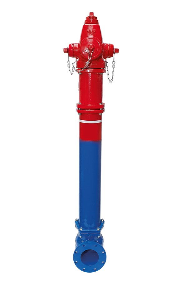
Dry barrel hydrant - Modern type to AWWA C502 - UL/ULC listed, FM approved - for fire protection application.
AVK Series 27 above-ground hydrants are equipped with a predetermined breaking point for easy repair after a collision or run over. The ductile iron core of the hydrant's main valve is completely surrounded by EPDM. Repairs and maintenance work on the upper part of the "dry barrel" hydrant can be carried out under pressure. The upper part of the hydrant can be rotated 360 degrees, steplessly. The hydrant series 27 are certified for high water pressures to 250 psi (PN17,2). Type RN hydrants are equipped with nuts, bolts and rods made of high-grade stainless steel (AISI 316/A4).
| Variant 27/RN-100 | |
|---|---|
| Connection: | Flanged |
| Material: | Ductile iron |
| DN: | DN150 - DN150 |
| PN: | 250 psi |
| Closing direction: | Clockwise to Close |
Features
- High pressure rating (250 psi)
- Inlet 6" (DN150)
- 2 x 2.5" NST hose nozzles + 1 x 4" NST pumper nozzle
- 1 1/2" pentagon operating nut
- 5.25" valve opening for high flow rating
- Ductile iron nozzle section, barrel section, bonnet, and base
- 360 degree upper part rotation possible, steplessly
- Breakable flange and stem rod coupling ensure no leaking and easy repair at traffic knock down
- Upper and lower stem rod Stainless steel AISI316 (A4)
- Hydrant drain easily plugged if required - may be plugged internally or externally
- Extensions available in lengths from 6' to 60' (steps of 1/2 foot)
- Flange bores optionally according to ANSI or PN16 (EN 1092-2)
- Fusion bonded epoxy coating in compliance with DIN 3476 part 1, GSK approved
- Upper part color: red RAL3000 (Polyester coating, UV resistant)
- Optional: Different colors for upper part available
Downloads
Reference nos. and dimensions:
| Reference no. | DN mm |
H5 mm |
H3 mm |
Theoretical weight/kg |
|---|---|---|---|---|
| 27-RN-I0205-0AJ0J-DC0006 | 150 | 1066,8 | 1902 | 161 |
| 27-RN-I0206-0000J-DC0006 | 150 | 1219,2 | 2054 | 167 |
| 27-RN-I0207-0000J-DC0006 | 150 | 1371,6 | 2207 | 178 |
| 27-RN-I0208-0000J-DC0006 | 150 | 1524 | 2359 | 194 |
| 27-RN-I0209-0000J-DC0006 | 150 | 1676,4 | 2511 | 202 |
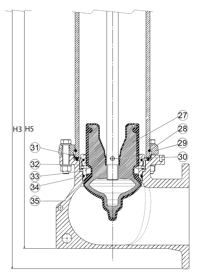
Components
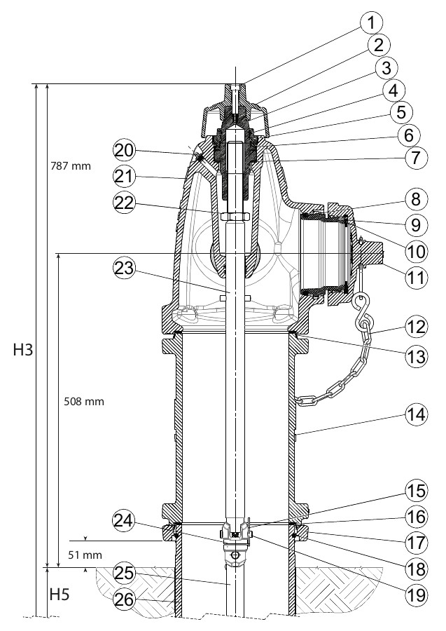
| 1. | Bolt | Stainless steel |
| 2. | Operation nut | Ductile Iron |
| 3. | Stem nut | Bronze |
| 4. | O-ring | NBR rubber |
| 5. | Thrust nut | Bronze |
| 6. | O-ring | NBR rubber |
| 7. | Anti-friction washer | PA |
| 8. | O-ring | NBR rubber |
| 9. | Outlet nozzle | Bronze |
| 10. | Flat gasket | NBR rubber |
| 11. | Cap | Grey iron |
| 12. | Chain | Steel, galvanized |
| 13. | Barrel gasket | NBR / stainless steel |
| 14. | Upper barrel | Ductile Iron |
| 15. | Spring split | Stainless steel |
| 16. | Barrel gasket | NBR / stainless steel |
| 17. | Breakable flange | Ductile Iron |
| 18. | Lock ring | Stainless steel |
| 19. | Split pin | Stainless steel |
| 20. | Grease nipple | Stainless steel |
| 21. | Nozzle section | Ductile Iron |
| 22. | Nut | Steel, galvanized |
| 23. | Upper stem rod | Stainless steel |
| 24. | Breakable coupling | Stainless steel |
| 25. | Lower stem rod | Stainless steel |
| 26. | Lower barrel | Ductile Iron |
| 27. | Main valve disc | Ductile iron, EPDM encapsulated |
| 28. | Lock ring | Stainless steel |
| 29. | Stand pipe flange | Ductile Iron |
| 30. | Split pin | Stainless steel |
| 31. | Barrel gasket | NBR / stainless steel |
| 32. | Drain Ring | Bronze |
| 33. | Valve seat ring | Bronze |
| 34. | O-ring | NBR rubber |
| 35. | Base | Ductile Iron |
Test/Approvals
- Hydraulic test according to AWWA C502, Shell test 500 PSI (2 x Working pressure)
- Approved according to CE Reg. No. 0620-CPR-6122
- Approved according to EN 14384
- Approved according to NSF-61, NSF International
- Approved according to NSF/ANSI Standard 372
- UL/ULC listed, FM Approved
Standards
- AWWA C502
- Flange drilling to ASME B16.1 class 125